
- Power Tools
-

Saws
Chain Saw Concrete Chain Saw Band Saw Reciprocating Saw ...
-

Cutters
Pneumatic Cutter Pipe Cutting Machine Nut Cutter
-

Drills
Hammer Drill Pistol Hammer Drill Two Hand Operation Drill Column Drill ...
-

Impact Wrenches
Pneumatic Impact Wrench (Ex-proof Series) Pneumatic Impact Wrench (Ultra light Series) Emulsion Impact Wrench Nut Runner ...
-
Torque Wrenches
Pneumatic Torque Wrench Electric Torque Wrench Hydraulic Torque Wrench Hollow Hydraulic Wrench ...
-

Mining Waterjet Cutting Machine
Electric Mining Waterjet Cutting Machine Pneumatic Mining Waterjet Cutting Machine Emulsion Mining Waterjet Cutting Machine
-

Hammers
Pneumatic Chipping Hammer Hydraulic Chipping Hammer
-

Scaler
Pneumatic Long Reach Scaler
-
Rammer
Pneumatic Rammer
-

Grinders
Wet Grinder Angel Grinder Electric Grinder
-

Fan
Pneumatic Fan Heavy Fixed Fan
-

Hoist
Chain Hoist Electric Hoist Pneumatic Hoist Hydraulic Hoist ...
-

Winch
Pneumatic Winch
-

Pump
Pneumatic Submersible Pump Emulsion Submersible Pump
-

Assembly
Torque Multipler C-Hog Ring Plier
-
- Accessories
-

Cutting
Chainsaw Concrete Chainsaw Band Saw Reciprocating Saw ...
-

Drilling
Impact Drills Light Drills Magnetic Drills丨Rail Drills Balance Drills丨Angle Drills ...
-

Assembly
Impact Wrenches C-Hog Ring Plier
-

Hammer & Shovel
Chipping Hammer Derusting Shovel
-

Grinding
Grinders
-

Hydraulic Accessories
Nut Runner Cutter
-

General Accessories
Waterjet Cutting Machine Filter assy. Filter assy. Water Pump ...
-
- Company Profile
- Service
- News
-

Events
The 21st 2023 Taiyuan Coal (En The 17th Yulin International C The 20th TaiYuan (2021) Coal ( The 16th Ordors International Have a machine repaired or hav ...
-

Case Study
Specifications of adjustable w Have a machine repaired or hav
-

Industry News
Using Chainsaws to Cut Snow? What to do if the pneumatic wr Hydraulic chain saw Operation of the wrench Introduction to the principle ...
-
- Download
- Contact


 You are here: >
Energy-saving structure and research of hydraulic equipment!Air band saw company
source:Industry News release time:2021-10-08 Article author:Rosit Popular:Air band saw
Energy-saving structure and research of hydraulic equipment
With the advancement and development of science and technology, the application of electro-hydraulic servo hydraulic systems (Hydraulic systems) in scientific research, experiments, engineering applications and other fields is becoming more and more extensive. However, with the development of the market economy and the widespread application, low efficiency and high operating costs have become very prominent problems. The main reasons are: (1) The flow and pressure of the oil source of the hydraulic system should be equipped according to the maximum load conditions or the maximum experimental capacity of the laboratory. In fact (Fact), the load conditions of the electro-hydraulic servo system are constantly changing, and the working time is often short under the maximum working conditions, and some equipment may even not use the maximum load at all. Many electro-hydraulic servo systems Work under small load conditions most of the time; at this time, only a small part of the flow of the hydraulic system oil source is used to meet the needs of the load speed, and most of the flow changes from the overflow valve to heat, which makes the oil temperature rise quickly . For example, a multi-channel electro-hydraulic servo system uses only part of the channels in many cases. On the other hand, in order to ensure the performance requirements of the system, the oil temperature needs to be controlled within a certain range (fàn wéi), so that the oil source system has to be equipped with a cooling device with sufficient heat dissipation area to cool the oil temperature. Caused a double waste.
")
(2) The electro-hydraulic servo system itself has a large throttling loss (loss).
(3) Loss of other hydraulic components of the system.
Therefore, when designing and configuring the electro-hydraulic servo system, especially for the electro-hydraulic servo system with larger power, energy-saving measures (referring to the solution to the problem) must be considered. Taking the electro-hydraulic servo control system of the "three-channel seismic isolation bearing detection equipment" designed and manufactured by the author for a university as an example, the energy-saving measures taken are introduced.
1 The principle of the system is introduced as shown. The system is a three-channel electro-hydraulic control system composed of 3 motors (advantages and applications of variable frequency electric locomotives). The load conditions are respectively 23000kN servo actuator, 1000kN servo actuator, 300kN servo actuator, the maximum working pressure of the system is set by the pilot relief valve, and the electro-hydraulic proportional relief valve remotely controls the working pressure of the system under different load conditions. The hydraulic servo valve is controlled by a computer to realize the frequency, amplitude and force control of the servo actuator.
It can be seen from the schematic diagram that the characteristics of the system are that the load conditions are very different, and the three servo actuators will not be used at the same time, but according to the size of the test piece, the material of the test piece (Material), and the nature of the test (destruction ( (vandalism), fatigue, detection, etc.) Choose (xuanze) different servo actuators for loading.
The principle of the three-channel current servo hydraulic system (Hydraulic systems) energy-saving measures (pointer to the solution to the problem) In order to reduce the energy loss (loss) of the electro-hydraulic servo system, the author has taken the following measures: (1) Set up independent cooling system. In order to ensure the working performance of the hydraulic system, the oil temperature must be controlled within a certain range (fàn wéi), and a cooler with sufficient heat dissipation area must be installed in the system to ensure that the oil temperature is
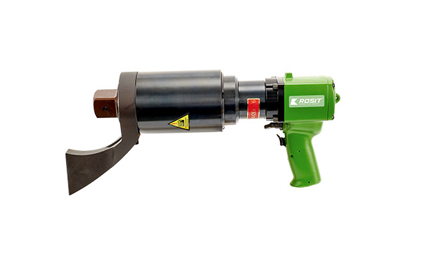
Control, it is best to set the cooling system separately. When the oil temperature is lower than the set temperature, the cooling system does not work; when the oil temperature is higher than the set temperature, the cooling system is started, which not only ensures the cooling system The real-time control of the system can also be controlled in real time according to the oil temperature changes when the system is working under different working conditions and different temperature conditions, which avoids starting the cooling system at the same time when starting the oil source system, and achieves the purpose of energy saving. The hydraulic wrench transmits power to the working head through the high-pressure oil pipe and the hydraulic pump, which drives the working head to tighten or loosen the nut. The hydraulic pump can be driven by electricity or compressed air. The working head of the hydraulic wrench is mainly composed of three parts, the frame (also called the shell), the oil cylinder and the transmission parts. The output force of the oil cylinder, the piston rod of the oil cylinder and the transmission part form a motion pair. The distance from the center of the oil cylinder to the center of the transmission component is the hydraulic wrench amplification arm. The oil cylinder output multiplied by the arm is the theoretical output torque of the hydraulic wrench. The actual output torque is smaller than the theoretical output torque.
(2) The main pump adopts a constant pressure variable pump. When the constant pressure variable pump is working, when the load speed decreases, the excess flow will increase the pressure of the main oil circuit. At this time, the constant pressure variable organization (organization) reduces the displacement of the variable pump under the effect of this pressure increase, so that the output flow of the oil pump is reduced, the pressure of the main oil circuit no longer increases, and it is maintained in a certain pressure range (fàn wéi); vice versa. Because the variable control device is used to make the output flow of the oil pump change with the change of the load, the purpose of energy saving is achieved.
(3) The main pump can also be a manual variable pump. When the system load is not large, manually adjust the flow rate of the axial piston pump (unit: cubic meters per second) to reduce the pump flow rate, so as to achieve the purpose of energy saving.
(4) Multiple motor pump sets are used. The author designed the No. 1 pump 60L/mi
N, No. 2 pump 100L/mi
N, No. 3 pump 160L/min 3 kinds of flow combinations, when designing the oil source system of the pumping station, especially the large flow system, consider the use of multiple motor pump sets as much as possible to divide the large flow into several small flow motor pump sets. A single pump set can be started under a small load. The equipment manufacturing cost may increase slightly, but its operating cost can be effectively reduced (reduce). On the other hand, if a single high-power motor is used Pump unit composition, its start-up will greatly increase the capacity and performance requirements of the power grid and electrical appliances, and the maintenance cost may greatly increase. In general, for large flow and high power oil source systems, multiple motor pumps are used in pairs. Maintenance is better than the setting of a single high-power and large-flow motor pump set.
(5) Set electro-hydraulic proportional relief valve. An appropriate electro-hydraulic proportional relief valve is set in the oil source system, and the system pressure is set according to the load condition to reduce the energy loss of the system.
(6) In the system, all hydraulic components, hydraulic valves and pipelines should be set to minimize the throttling loss (loss).
Read recommendations:
DM21-045 Pneumatic Magnetic Drill
related articles
Using Chainsaws to Cut Snow?
2024-05-21What to do if the pneumatic wrench is weak
2022-12-19Hydraulic chain saw
2022-12-13Operation of the wrench
2022-12-06Introduction to the principle of pneumatic wrench
2022-11-28How to use the pneumatic wrench
2022-11-21Brief introduction to the principle of pneumatic wrench
2022-11-14Impact pneumatic wrench
2022-11-07Correct hydraulic wrench operation procedure
2022-11-01Hydraulic wrench torque pressure conversion
2022-11-01Field operation procedure of hydraulic wrench
2022-10-24Hydraulic radial plunger motor
2022-10-17The history of hydraulic motors
2022-10-17Principle of balance hydraulic wrench
2022-10-10The Price Factor of Smart Electric Torque Wrench
2022-10-10Introduction to the advantages of using intelligent electric torque wrench
2022-10-10The Price Factor of Smart Electric Torque Wrench
2022-10-10Classification and use of wrenches
2022-10-10hydraulic wrench pressure conversion
2022-10-10Introduction to the advantages of the use of intelligent electric torque wrench
2022-10-10Smart Electric Torque Wrench Selection Guide
2022-10-10Intelligent electric torque wrench for wind power generation
2022-10-09Uses of open-end wrenches.Pneumatic chainsaw
2022-10-08What are the driving parts of a hydraulic wrench and what they do
2022-09-30What are the driving parts of a hydraulic wrench and what they do
2022-09-23the commonly used wrenches
2022-09-22Introduction of several common wrenches
2022-09-21Application scope and daily maintenance method of hydraulic bolt tensioner
2022-09-20Characteristics of hollow hydraulic wrench and precautions for use
2022-09-19Characteristics and precautions of driving hydraulic wrench
2022-09-17Power Tools
CB22-210 Pneumatic Band Saw - Stainless Steel Series
2023-05-18CN22-110130 Nut Cutter丨Split-type Nut Cutter
2023-06-17CN22-2434 Nut Cutter丨Split-type Nut Cutter
2023-06-17AN32-2500 Hollow Hydraulic Wrench
2022-12-27OF25-260 Pneumatic Fan (light/medium)
2023-06-28AN11-600 Electric servo CNC Torque Wrench
2022-12-20CB22-200 Pneumatic Band Saw - Stainless Steel Series
2023-06-16DC31-300 Hydraulic Core Drill
2023-06-20CF21-018 Pneumatic Cutter
2023-06-17GP61-050 Emulsion Submersible Pump
2022-12-29RZ21-014 Pneumatic Rammer
2022-12-28DP61-110 Emulsion Two Hand Operation Drill
2022-12-14AN51-4000 Electric servo CNC Torque Wrench
2023-06-27RC21-850 Pneumatic Long Reach Scalers
2023-06-27CC21-630 Pneumatic Chainsaw (3.0 kw Series)
2023-06-14AN22-750 Pneumatic Torque Wrench (Straight Shank)
2020-06-13AN22-4500 Pneumatic Torque Wrench (Straight Shank)
2021-06-03CB61-160丨Emulsion Band Saw
2023-06-17LW21-010 Pneumatic Winch
2023-01-06AN21-300 Pneumatic Nut Runner
2022-12-20AN31-7500 Hydraulic Torque Wrench
2023-06-27AN71-10000 Torque Multiplier
2023-06-29DC11-300 Electric Core Drill
2023-06-20OW21-020 Pneumatic Mining Waterjet Cutting Machine
2023-05-10DA21-050 Pneumatic Angle Drill
2023-06-19CB22-160 Pneumatic Band Saw - Stainless Steel Series
2023-06-16LH61-020 Emulsion Hoist
2023-06-29AK22-110 Pneumatic C-Hog Ring Plier (2.0 coil)
2023-06-29DB21-050 Pneumatic Rotary Drill Heavy Duty
2023-06-19GG11-230 Electric Angle Grinder
2023-06-28Accessories
Guide Bars
2023-06-06Platform Clamps丨CB863-19
2023-06-06Alloy Sleeves (Square to Outer Hexagonal)
2023-06-07Carborundum saw Blades
2023-06-06Alloy Saw Chains丨CC812/CC816 Series
2023-06-06Tool Bits
2023-06-07Rail Clamps丨CB864-12
2023-06-06Carbide Hollow Bits丨DM818 Series
2023-06-06Optional Accessories
2023-06-07Alloy Saw Blades
2023-06-06Hard Alloy Hollow Drill Bits assy.丨DB85 Series
2023-06-07Alloy Drill Bits丨812 Series
2023-06-06Split Hollow Drill Bits丨DC82
2023-06-07Carborundum Saw Chains
2023-06-06Alloy Twist Drill Bits丨DB81 Series
2023-06-06Carbide Inserts Twist Bits assy.丨DB83 Series
2023-06-07Alloy Drill Bits丨811 Series
2023-06-06Diamond Saw Blades
2023-06-06Pipe Fixed Clamps丨CB861-18
2023-06-06Abrasive Blades
2023-06-07Grinding Disc
2023-06-07Alloy Saw Blades丨CR812 Series
2023-06-06Sleeve KIT
2023-06-07Clamps
2023-06-06Hydraulic Regulating Valve
2023-06-07Carbide Inserts Twist Bits丨DB82 Series
2023-06-06Carbide Hollow Rail Drill Bits丨DM822 Series
2023-06-06Alloy Sleeves
2023-06-07Alloy Saw Blades
2023-06-06Tool Bits
2023-06-07


